Usage
Quick start guide
- Below are a few steps to help you get started
- Turn on the CLEON device
- Connect CLEON to PC using USB cable
- Launch PC based software 'CLEON_Connector' for time sychronization and user parameter update
- In the 'CLEON_Connetor', change user paramters to desired values
(If there's an error for the value of parameter, it is impossible to update user parameters)
(Although battery capacity is used as parameter, this is used only to calculate rough estimate whether desired number of samples can be captured with the capacity) - Select the COM port that CLEON is connected to
- Then, press 'Connect' button
- Once COM port is successfully opened, 'Connect to CLEON (1/3)' button will be enabled
- Once CLEON is successfully connected, 'Connect to CLEON (1/3)' button will be changed to 'Update parameters (2/3)'
- Press 'Update parameters (2/3)' to update CLEON with user parameters (sample count, sample gap, chunk count, chunk gap)
- Once user parameters are successfully updated, 'Update parameters (2/3)' button will be changed to 'Update CLEON time tick (3/3)'
- Press 'Update CLEON time tick (3/3)' to update CLEON system time (RTC time and millisecond time tick)
- 'CLEON_Connector' will notify of successful update by showing 'Time tick sent successfully' in status bar
- Now that user parameters are updated and CLEON system time is synchronized, CLEON is ready to capture GPS and sensor data
- Press user-button on CLEON to start logging
- If MicroSD is properly inserted, CLEON starts to log GPS and sensor data repeatedly as defined
- At the first time, CLEON creates directory named 'CLEON' in MicroSD card and creates log file whose name is starting with current time tick under the directory 'CLEON'
- The file will remain opened until defined number of GPS and sensor data is logged and written
(meaning that data will be appended to the opened file)
(This is to save energy consumed by seeking access to MicroSD) - If defined number of samples are captured, new file will be created for next logging
- If MicroSD card is suddenly removed, MicroSD error LED will be turned on (however, data captured until error will remain uncorrupted)
- If MicroSD is inserted back to the slot again, CLEON will initialze the file system again
LED Indicator
- There are 6 LEDs between MicroSD card slot and JTAG header
- Let's call the LEDs as LED1 to LED6 from the leftmost LED which is closest to MicroSD card slot
- LED1 and LED3 are used to indicate errors
(If everything goes well and GPS signal is ready to be captured, LED1 and LED3 should be automatically turned off by the firmware)- LED1
- ON : MicroSD is missing
- OFF : MicroSD is in the slot
- LED2
- ON : GPS signal is being captured
- OFF : GPS signal is not being captured
- LED3
- ON : Time is not synchronized
- OFF : Time is synchrinized
- LED4
- N/A
- LED5
- N/A
- LED6
- ON : GPS is not functioning
- OFF : GPS is operational
- LED1
System time
- CLEON maintains two distinct system time: Time tick and RTC time
- Time tick
- Mainly used for GPS and sensor data time stamp
- Set to zero when initial power-up
- Need to be synchronized with UTC time tick in DateTime format
(http://msdn.microsoft.com/en-us/library/system.datetime.ticks.aspx)
(10,000 tick is equal to 1 millisecond) - Variables used: uniSecondTimeTick, uniMillisecondTimeTick
- 'uniMillisecondTimeTick' is incremented by 10,000 in every millisecond
- 'uniSecondTimeTick' is incremented by 10,000,000 in every second
- By combining those two, it is possible to get current CLEON UTC time tick
- RTC time
- Mainly used for FAT file system time stamp
- Set to 00:00:00 of 1-Jan-1980 when initial power-up (Time synchronization required)
- Generates an interrupt in every second
- In this ISR, 'uniSecondTimeTick' is incremented by 10,000,000 and 'uniMillisecondTimeTick' is reset to zero
- Time tick
- Maintaining synchronized time
- Once time synchronization message is received, CLEON stores the pair of RTC time and time tick to internal FLASH for future use
- The synchronized time (both RTC time and time tick) is maintained even when primary power supply (in our case, LiPo battery) is drained out
- MSP430 has SVSH, which supervises the primary supply (in our case, LiPo battery)
- When the primary supply falls below the configured SVSH level, SVSH initiates backup system and puts MSP430 into reset state (SVSH(POR))
(Currently, SVSH voltage is set to 2.04V) - When backup system is in place, RTC is powered by backup battery (VBAT) and kept running even when the primary supply fails
(WARNING!!) (Note that this scenario is NOT applicable to sudden battery removal becuase MSP430 requires some time to initiate backup system) - Once CLEON is powered up again, CLEON retrieves the time information, which was stored into internal FLASH when synchronization message was received
- CLEON restores current UTC time tick by adding the difference between current and stored RTC time to previously stored UTC time tick
(Note that time synchronization error LED will be turned on if there's a problem in time synchronization or restoration)
USB frame
- USB frame is used for exchanging data between CLEON and USB host (typically, PC)
- USB frame is 36 bytes in total
- USB frame starts with 2 bytes(0x55) of header and ends with 2 bytes(0xAA) of footer
- Length fields includes the length of data plus one (meaning that length field itself is considered as data)
- There should be an ACK for every data frame exchanged
- The figure below decribes the format of the USB frame
- USB data frame

- USB ack frame

- USB data frame
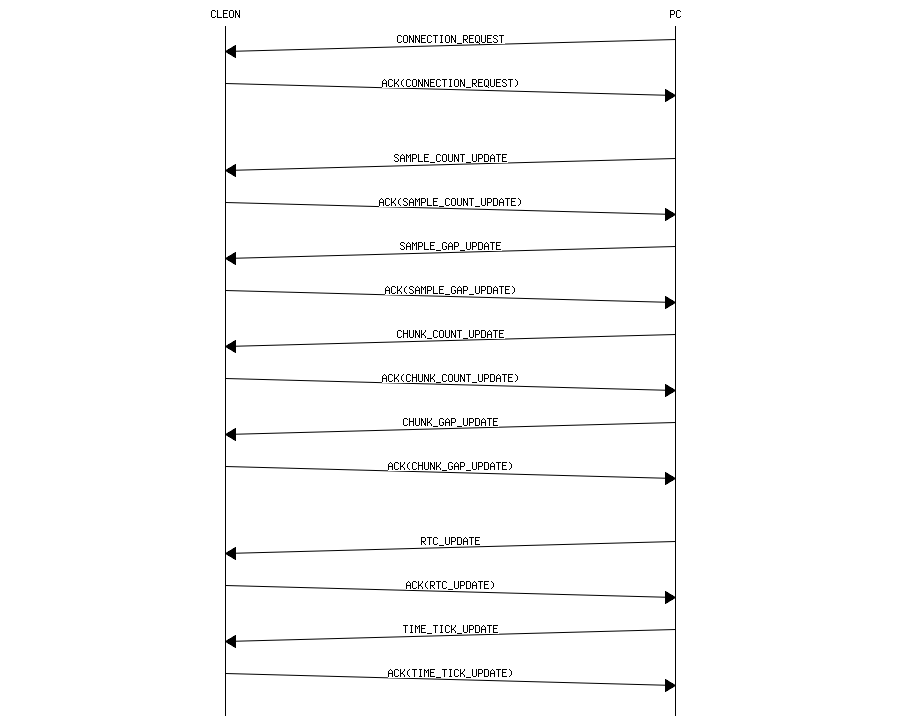
- Time synchronization message is exchanged by using USB
- The sequence chart below describes the communication between CLEON and PC

