Usage
Explanation
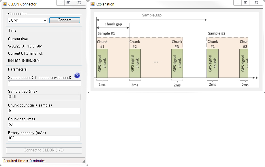
- Each sample consists of several 2ms GPS signal chunks
- The figure below is the screenshot of the 'CLEON CONNECTOR'
(The figure includes a window for 'Explanation' which is popped up if you click the question mark icon) - If there's an error, the SW indicates the error with red colored text

- Connection
- This will list all the available COM port on your PC
- Select the port that your CLEON is connected to and click 'Connect' button to establish connection to CLEON
- Time
- In the time group, it shows current time and UTC time tick
- You can find more information about UTC time tick here
(http://msdn.microsoft.com/en-us/library/system.datetime.ticks.aspx)
- Parameters
- In the parameters group, you can set parameters to user defined value
- Sample coount ('1' means on-demand)
- If default 'Sample count' 1 is used, CLEON capture GPS signal on demand upon pressing user button
- Otherwise, you can set user defined value
- Sample gap(ms)
- If 'Sample count' is greater than 1, you can define 'Sample gap' in milliseconds
- 'Sample gap' should be multiple of 1000 (ms)
- Chunk count (in a sample)
- Number of chunks in a sample
- Chunk gap (ms)
- Time betweem chunk
- 'Chunk gap' should be at least 50 (ms)
- Battery capacity (mAh)
- 'CLEON CONNECTOR' will calculate whether the user defined number of samples can be captured with given battery capacity
- Use this as referential purpose only
- Connection
Quick start guide
- Below are a few steps to help you get started
- Turn on the CLEON device
- Connect CLEON to PC using USB cable
- Launch PC based software 'CLEON CONNECTOR' for time sychronization and user parameter update
- In the 'CLEON_CONNECOTR', change user paramters to desired values
(If there's an error for the value of parameter, it is impossible to update user parameters)
(Although battery capacity is used as parameter, this is used only to calculate rough estimate whether desired number of samples can be captured with the capacity) - Select the COM port that CLEON is connected to
- Then, press 'Connect' button
- Once COM port is successfully opened, 'Connect to CLEON (1/3)' button will be enabled
- Once CLEON is successfully connected, 'Connect to CLEON (1/3)' button will be changed to 'Update parameters (2/3)'
- Press 'Update parameters (2/3)' to update CLEON with user parameters (sample count, sample gap, chunk count, chunk gap)
- Once user parameters are successfully updated, 'Update parameters (2/3)' button will be changed to 'Update CLEON time tick (3/3)'
- Press 'Update CLEON time tick (3/3)' to update CLEON system time (RTC time and millisecond time tick)
- 'CLEON CONNECTOR' will notify of successful update by showing the value of sent tick
- Now that user parameters are updated and CLEON system time is synchronized, CLEON is ready to capture GPS and sensor data
- Press user-button on CLEON to initiate logging
- If MicroSD is properly inserted, CLEON starts to log GPS and sensor data repeatedly as defined
- At the first time, CLEON creates directory named 'CLEON' in MicroSD card and creates log file whose name is starting with current time tick under the directory 'CLEON'
- The file will remain opened until defined number of GPS and sensor data is logged and written
(meaning that data will be appended to the opened file)
(This is to save energy consumed by seeking access to MicroSD) - If defined number of samples are captured, new file will be created for next logging
- If MicroSD card is suddenly removed, MicroSD error LED will be turned on (however, data captured until error will remain uncorrupted)
- If MicroSD is inserted back to the slot again, CLEON will initialze the file system again
LED Indicator
- There are 6 LEDs between MicroSD card slot and JTAG header
- Let's call the LEDs as LED1 to LED6 from the leftmost LED which is closest to MicroSD card slot
- LED1 and LED3 are used to indicate errors
(If everything goes well and GPS signal is ready to be captured, LED1 and LED3 should be automatically turned off by the firmware)- LED1
- ON : MicroSD is missing
- OFF : MicroSD is in the slot
- LED2
- ON : GPS signal is being captured
- OFF : GPS signal is not being captured
- LED3
- ON : Time is not synchronized
- OFF : Time is synchrinized
- LED4
- N/A
- LED5
- N/A
- LED6
- ON : GPS is not functioning
- OFF : GPS is operational
- LED1
USB frame
- USB frame is used for exchanging data between CLEON and USB host (typically, PC)
- USB frame is 36 bytes in total
- USB frame starts with 2 bytes(0x55) of header and ends with 2 bytes(0xAA) of footer
- Length fields includes the length of data plus one (meaning that length field itself is considered as data)
- There should be an ACK for every data frame exchanged
- The figure below decribes the format of the USB frame
- USB data frame

- USB ack frame

- USB data frame
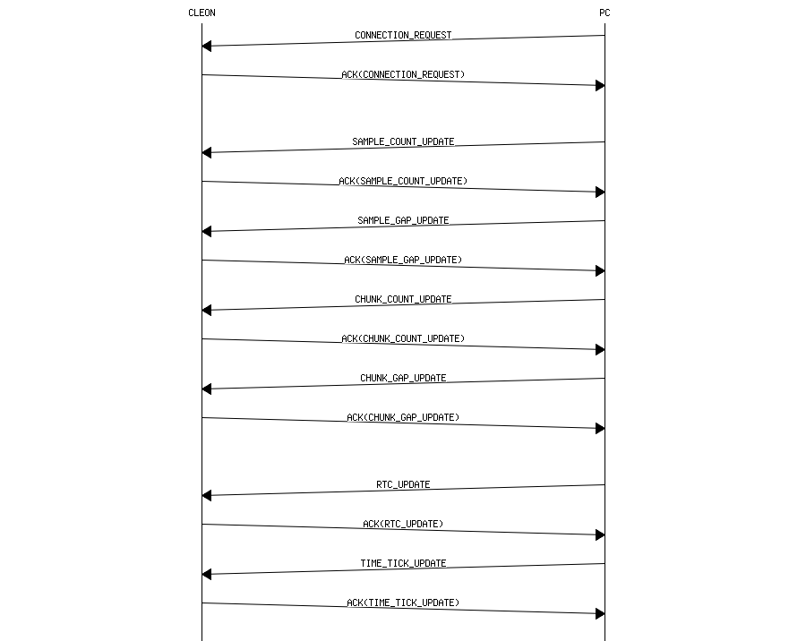
- Time synchronization message is exchanged by using USB
- The sequence chart below describes the communication between CLEON and PC

